Recently we have presented our research on the remote exploitation of Huawei basebands at Black Hat USA 2021. As part of our findings, we have identified several bootloader vulnerabilities in Huawei Kirin chipsets. In addition to that publication, we have also recently disclosed an additional bootrom vulnerability (CVE-2021-22429) in Huawei Kirins.
As it has been publicized, many of these bootloader vulnerabilities were present in bootrom code. As such, it can come as a surprise that Huawei in fact created a mitigation which was published just before Black Hat, in a July OTA update (updates started from June 29th, to be precise).
In this post, we describe how we reverse engineered the OTA to figure out how it prevents the exploitation of the bootrom vulnerabilities and how we in turn figured out a way to bypass the mitigation and maintain control of a device while also applying the OTA.
Primer: The BootROM Vulnerabilities
Our whitepaper contains all the background information on the bootloader vulnerabilities. As a very brief summary, the key component is the feature of the Huawei bootloader stack called USB Download Mode. As described elsewhere, during the regular boot sequence, Huawei’s BootROM initializes the UFS hardware and the crypto engine in order to load and verify the next stage bootloader image from flash. However, when run in download mode, which maybe used for factory flashing and repair purposes, a connected host can communicate with the BootROM via USB.
The vulnerabilities that we have identified (CVE-2021-22429, CVE-2021-22426, CVE-2021-22433, CVE-2021-22434) were all reachable via this USB interface. Many of these issues were present in several stages of the bootloader and in multiple Kirin chipset generations.
Luckily, in the case of the newest Kirin chipset family (Kirin 9000), Huawei received our initial reports in time for them to apply codefixes both at the bootROM and xloader level before the first devices with Kirin 9000 ever came out.
In the case of older affected chipsets such as Kirin 980 and Kirin 990, fixes for the issues in the xloader code were also published a while ago, specifically in OTAs starting in September 2020.
The most interesting issues that this post is concerned with were the ones that affected the bootrom of Kirin 990. In summary, these were:
- CVE-2021-22433: this CVE rolled three issues into one id. Out of these, the two issues affecting the Kirin 990 bootrom are described in section 2.7.2. and 2.7.4. of our white paper.
- CVE-2021-22434: this issue is described in detail in section 2.7.5. of our white paper.
- CVE-2021-22429
There Is No Try: Installing The OTA
On June 16th, we received communication from Huawei stating that they have found a mitigation for the remaining issues and the distribution via OTA will start by next month. On June 29th, they have confirmed that the OTA roll-out has started. We had some initial theories on what Huawei may or may not have done (see the next section for some more clarity on this subject), but ultimately we decided that the best course of action is to cleanly apply an OTA and check out the results. Basically we felt that hunting for changes in various firmware images when we don’t even know for certain what it is that we are supposed to look for might turn out to be a futile exercise. In hindsight, we might have been able to reach our conclusions without “burning” a device, but at the time, we decided that we’re just going to do it and see what happens.
The test phone we used was a Huawei Mate 30 Pro (LIO), initially on the 11.0.0.168 firmware version.
Sometime in July the OTA notification has arrived, showing that a newer version (11.0.0.188) is available to download.
At this point we went ahead and applied the update just as any other user would have done: from the settings menu, system & updates, software updates option.
The download and installation process was completely regular, no sign that anything special would be happening and after the phone has successfully rebooted, we’ve confirmed that the version number incremented to 11.0.0.188.
Next, to test the BootROM vulnerabilities, we rebooted the phone to try and put it into Download Mode. This is where we ran into a slight issue :) Although we triggered the Test Point, the phone didn’t enumerate as a USB device. Because the Test Point is so tiny, there are occasions when the phone doesn’t register the trigger for the first try. So we force-restarted with holding down the power key, but we similarly failed to enter the Download Mode for the subsequent trials.
After a number of tries, we were able to conclude that the Test Point detection still works (that is when the Test Point is triggered an alternate boot path is selected), but for some reason the USB refuses to enumerate. That is to say, the boot process locks up and stays frozen when the Test Point is triggered, but without the trigger the phone boots up successfully.
At this point, we can conclude that the update in effect kills the USB Download Mode as a whole, which makes it an effective mitigation: if the vulnerable mode of execution can not be reached at all, the vulnerabilities can’t be exploited. We were still left with the task of figuring out how Huawei pulled this off and what precisely is the effect.
It is worth stopping here for a second and realizing the implications of this type of fix. The idea of allowing a USB Download Mode in the bootrom is to provide an engineering backup in case a device goes into a “soft-brick” status - which is to say that for some reason the xloader image in the UFS gets corrupted (due to e.g. an erroneous UFS overwrite, such as a failed update). If Huawei turns this mode of operation in the bootrom off for good, a device can no longer be revived via any method (known to us) in case such a UFS corruption occurs. In other words, this OTA comes at a cost.
ARM’s FPB Or How NOT To Fix BootROM Bugs Via OTA
As we mentioned above, we had some thoughts on how BootROM code of an ARM core might be patched in geneal. In this section, we examine ARM’s default facility for this and explain why it was not a viable option for Huawei in this case.
The early bootloader stages, such as the BootROM itself as well as the xloader run on an ARM Cortex-M3 microcontroller.
Embedded ROM code is actually very common for MCUs, and by nature it is pricy for the vendor to modify a mask-programmed ROM when e.g. they want to fix a bug.
But bugs are common even in ROMs, so ARM developed a solution for this case: the FPB subsystem.
FPB is stands for Flash Patch and Breakpoint Unit, and at first it could be confusing why the patch functionality is mixed with a debugging feature.
Well, both of them have something in common: they are implemented with a comparator on the program counter (or address of the data memory bus), and only differ in the trigger action in case of a comparation match.
The Flash Patch subsystem consists of multiple slots with a configurable replacement address, and when the execution reaches that address, the FPB replaces the original content with a new one.
The replacement content unit is 4 bytes (with special handling for not-aligned Thumb code) and it is stored on modifiable memory, the SRAM region, which is located at the 0x20000000 range with ARM’s defaults.
When we analyzed the status of FPB in Kirins, we found that Huawei does in fact utilize the FPB unit of the Cortex-M3, but in a rather exotic way.
The memory layout of the BootROM does not align with the hardcoded 0x20000000 SRAM base address, because the SRAM begins at 0x20000 instead.
So as a workaround there is a tiny memory (probably backed by pure registers) at 0x20000000 to hold the FPB replacement values.
The FPB is configured from efuse values, so by nature those can be only modified once. There are two sections in the efuse regarding the FPB. One for the addresses whose content is to be replaced and the other for the replacement content itself. There is an other type of patch, let’s call it an “extended” patch, for replacement content not fitting in the 4-byte slot. Such extended patches get copied into a specified location in the RAM.
Most of the efuse values which are multi-bit (e.g. a number or a byte-string) are checksumed. The employed checksum simply stores the number of zeros over the bits of the content, which is amusingly clever. The efuse bits are initially all zeroes, and only the zero-to-one transition is allowed by the physics of the fuse. So the zero values can only decrement, but it is impossible to decrement a binary value by zero-to-one transitions.
Below is the FPB configuration routine, which reads the efuses, computes and verifies the zero-count checksum, and finally loads the FPB values into the memory-mapped FPB interface of the Cortex-M3.
int FPB_setup(uint *has_extended_patch)
{
  ushort fpb_data[24];
  uint fpb_zerocount;

  uint *data_ptr = &fpb_data;
  // read the FPB data from the efuse (0xd words are read)
  if (read_efuse(&fpb_data, 0xd, 0x4c)) {
    cprintf("rFPerr\n");
    return -1;
  }

  // compute the zero-count checksum
  do {
    current_val = *data_ptr - (*data_ptr >> 1 & 0x55555555);
    current_val = (current_val >> 2 & 0x33333333) + (current_val & 0x33333333);
    data_zero_cnt += (0x20 - ((current_val + (current_val >> 4) & 0xf0f0f0f) * 0x1010101 >> 0x18));
    data_ptr = data_ptr + 1;
  } while (data_ptr != (uint *)(fpb_data + 0x16));

  if (fpb_zerocount & 0xf) {
    // check if it has extended patches
    *has_extended_patch = 0x5555aaaa;
  }

  // check zero-count checksum
  if (data_zero_cnt != (fpb_zerocount << 0x10) >> 0x14) {
    cprintf("FP_Z_err!\n");
    return -1;
  }

  uint idx = 0;
  do {
    // apply the FPB data via the FPB memory mapped interface
    (...)
  } while (idx != 8);

  return 0;
}
The zero-count checksum mismatches are handled as faults, so the ARM FPB entries are not populated. This also means that, if done correctly, the FPB efuse values can only be written once, at the factory, because any subsequent write (albeit the efuse bits can be written!) would result in a bogus zero-count value, and thus no FPB would be applied.
Armed with that knowledge, we have previously analyzed the FPB efuse values in Kirin 990s and found that while the efuse bits are fully zeroed out, the checksum counter was also set to the maximum value:
FP_COMP0                  [2432:2448]: 0x00000000 (0)
FP_COMP1                  [2448:2464]: 0x00000000 (0)
FP_COMP2                  [2464:2480]: 0x00000000 (0)
FP_COMP3                  [2480:2496]: 0x00000000 (0)
FP_COMP4                  [2496:2512]: 0x00000000 (0)
FP_COMP5                  [2512:2528]: 0x00000000 (0)
FP_COMP6                  [2528:2544]: 0x00000000 (0)
FP_COMP7                  [2544:2560]: 0x00000000 (0)
FP_REMAP0                 [2560:2592]: 0x00000000 (0)
FP_REMAP1                 [2592:2624]: 0x00000000 (0)
FP_REMAP2                 [2624:2656]: 0x00000000 (0)
FP_REMAP3                 [2656:2688]: 0x00000000 (0)
FP_REMAP4                 [2688:2720]: 0x00000000 (0)
FP_REMAP5                 [2720:2752]: 0x00000000 (0)
FP_REMAP6                 [2752:2784]: 0x00000000 (0)
FP_REMAP7                 [2784:2816]: 0x00000000 (0)
FP_EXTENDED               [2816:2820]: 0x00000000 (0)
FP_ZEROCOUNT              [2820:2832]: 0x00000180 (384)
This guarantees that no more patches can be added into FPB post-factory. That’s the reason we believed that an out-of-the-factory customer Huawei smartphone with Kirin chipset can’t be patched for BootROM bugs via FPB.
Hunting For Clues: Diffing The Xloader
At this point, we were completly clueless how Huawei managed to realize this patch. As our only hope we decided to look for changes between the current and the previous firmware versions, where USB Download Mode was known to be working. We thought that the earliest and thus more privilegized firmwares have a higher chance of having something to do with this patch, so we selected the xloader, fastboot, bl2 and trustfirmware images. Luckily, as we have concluded before, any device with an equivalent chipset can be used as a decryption oracle for encrypted firmwares. Therefore, despite losing our platform control on this particular Mate 30, we were still able to leverage other devices for decrypting firmware images of the newest OTAs. As it turns out, diffing firmware binaries in a meaningful way in this case was not a trivial task, even between not-so-distant versions. Ghidra’s version tracking and Bindiff did not present any useful clues for an obvious patch in either firmware, because the signal-to-noise ratio of their findings was too low for a lead. Instead we turned to byte-level diffing with a clever tool called biodiff. Biodiff is able to automatically re-align input files to achieve a maximal overlap, so it can handle inserted or removed bytes gracefully. Here is the output of biodiff for the xloader firmware where we encountered the first major difference.
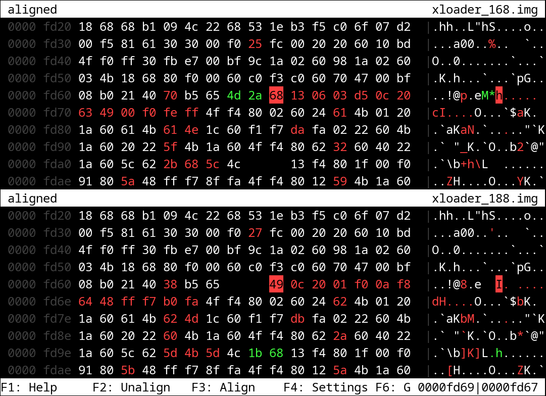
By examining the context of this change, we found that the patch is located in the beginning of a function related to USB initialization.
We originally called this function usb_clk_and_power_init, because it seems like clocking, gating, and power initialization happens inside.
This function is reachable on the following call path in xloader (11.0.0.188):
- usb_clk_and_power_init
  - usb_init
    - usb_download_init
      - get_uce
      - get_fastboot
For comparison, here is the relevant Ghidra decompiled snippet at the beginning of the function, before the update (11.0.0.168):
void usb_clk_and_power_init(void)
{
  uint uVar1;
  int iVar2;

  /* ============ ORIGINAL ============ */
  iVar2 = read_volatile_4(SCTRL_SCDEEPSLEEPED);
  if (iVar2 << 0x18 < 0) {
    set_bit_at_address(0xc,0xb818160c);
  }
  /* ================================== */
  _DAT_40281380 = 0x400000;
  _DAT_b8581020 = 0x60;
  udelay(1);
  _DAT_40285040 = 2;
  _DAT_40285050 = 0x400;
  _DAT_b8581000 = 0x40;
  _DAT_b8581024 = 0x60;
  uVar1 = read_volatile_4(SCTRL_SCDEEPSLEEPED);
  if ((uVar1 & 0x100000) == 0) {
    _DAT_40285148 = 0x800;
    _DAT_be02e010 = 0x10001;
    udelay(10);
    _DAT_be02e064 = _DAT_be02e064 & 0xfdffffff;
  }
  else {
    cprintf("[USBI]use pad clk\n");
    _DAT_402850cc = 0x100000;
    _DAT_4028570c = 0x10001;
    _DAT_40285050 = 0x80;
    _DAT_be02e064 = _DAT_be02e064 | 0x2000000;
  }
  (...)
And this is the same function, after the update (11.0.0.188):
void usb_clk_and_power_init(void)
{
  uint uVar1;
  int iVar2;

  /* ============ PATCH ============ */
  clear_bit_at_address(0xc,(uint *)0xb818160c);
  cprintf("[USBI]clear usb vregbypass\n");
  /* =============================== */
  _DAT_40281380 = 0x400000;
  _DAT_b8581020 = 0x60;
  udelay(1);
  _DAT_40285040 = 2;
  _DAT_40285050 = 0x400;
  _DAT_b8581000 = 0x40;
  _DAT_b8581024 = 0x60;
  uVar1 = read_volatile_4(SCTRL_SCDEEPSLEEPED);
  if ((uVar1 & 0x100000) == 0) {
    _DAT_40285148 = 0x800;
    _DAT_be02e010 = 0x10001;
    udelay(10);
    _DAT_be02e064 = _DAT_be02e064 & 0xfdffffff;
  }
  else {
    cprintf("[USBI]use pad clk\n");
    _DAT_402850cc = 0x100000;
    _DAT_4028570c = 0x10001;
    _DAT_40285050 = 0x80;
    _DAT_be02e064 = _DAT_be02e064 | 0x2000000;
  }
  (...)
As we can see, the behavior regarding the address 0xb818160c has changed and a new debug log message has appeared!
The new code always clears the 12th bit at that address, whereas beforehand that bit was set only when reading a one-bit from the SCDEEPSLEEPED register.
SCDEEPSLEEPED is located at 0x4021b008 (from LPMCU memory view) so it is one of the SCTRL configuration registers.
In the published LIO kernel sources there is a soc_sctrl_interface.h header file, describing the SCTRL interface (this is also how we got the register’s name that we used to label the decompiled code), where the +0x008 offset is described as follows:
typedef union
{
    unsigned int value;
    struct
    {
        unsigned int deepsleeped   :  1;
        unsigned int reserved_0    :  1;
        unsigned int reserved_1    :  1;
        unsigned int reserved_2    :  1;
        unsigned int sleeped       :  1;
        unsigned int reserved_3    : 15;
        unsigned int reserved_4    : 11;
        unsigned int kce_auth_pass :  1;
    } reg;
} SOC_SCTRL_SCDEEPSLEEPED_UNION;
Cross checking this register description among older kernel sources for different models version yielded another interesting finding:
typedef union
{
    unsigned int      value;
    struct
    {
        unsigned int  deepsleeped     : 1;  /* bit[0]    : ...             */
        unsigned int  reserved_0      : 3;  /* bit[1-3]  : ...             */
        unsigned int  sleeped         : 1;  /* bit[4]    : ...             */
        unsigned int  reserved_1      : 15; /* bit[5-19] : reserved_efuse1 */
        unsigned int  reserved_2      : 11; /* bit[20-30]: reserved_efuse0 */
        unsigned int  reserved_3      : 1;  /* bit[31]   : ...             */
    } reg;
} SOC_SCTRL_SCDEEPSLEEPED_UNION;
The two bitmaps align well, so based on the comment we conclude that bit 5 to 19 are in fact backed by an efuse, probably this is an alternative view on a specific range of the efuse values.
At this point, we did not know what this efuse is, but we had the address of it, so for the firmware version before the 188 update, we were able to verify that the bit in question in the efuse used to be zero.
In other words, the original set_bit_at_address call has never run before.
(Obviously since we haven’t bypassed the new mitigation at this point, we weren’t yet able to verify that this efuse in fact got burned by the OTA. We did do that successfully later.)

Bootrom Parallels: Understanding The Kill Switch
So we have analyzed the xloader code so far. It gave us a useful hint, but the USB Download Mode fails in bootrom already, so the question was, what could have changed there?
At this point, we looked for the same usb_clk_and_power_init in the bootrom and sure enough we found a basically identical code:
void bootrom_usb_clk_and_power_init(void)
{
  /* test the 7th bit (0 indexed), mask: 0x80 */
  if ((int)(SCDEEPSLEEPED << 0x18) < 0) {
    _DAT_b818160c = _DAT_b818160c | 0x1000;
  }
  _DAT_40281380 = 0x400000;
  _DAT_b8581020 = 0x60;
  udelay(1);
  _DAT_40285040 = 2;
  _DAT_40285050 = 0x400;
  _DAT_b8581000 = 0x40;
  _DAT_b8581024 = 0x60;
  FUN_000031e0();
  FUN_000032a0();
  if ((int)(SCDEEPSLEEPED << 4) < 0) {
    _DAT_b8181600 = _DAT_b8181600 & 0xfffffcff;
  }
  else {
    _DAT_b8181600 = _DAT_b8181600 | 0x300;
  }
  (...)
There it is, the same behavior!
This gave us the theory that the 7th bit of the SCDEEPSLEEPED register must have changed as the result of the OTA update and that change now means that the 0xb818160c value gets initialized differently (set as opposed to not getting set) during USB controller bring-up.
The log message, specifically, told us that this system control register bit is something called a VREGBYPASS.
Armed with the knowledge of the particular efuse and sysctrl addresses, we looked for hints in kernel sources.
In soc_lpmcu_baseaddr_interface.h we found a reference to this sysctrl range, which is called HSDT_SYS_CTRL.
#define SOC_LPMCU_HSDT_SYS_CTRL_BASE_ADDR (0xB8181000)
Sadly there’s no detailed interface description header file for the HSDT_SYS_CTRL range, like the SCTRL has, so we can’t just look up the meaning of the +0x060c offset.
At this point, based on its name and public Huawei kernel sources we found that there were similarly named USB register bits in past kernel versions for the same DWC USB controller.
In the example below the comment suggests that based on the state of the VREGBYPASS bit, a different power rail (here 1.8V or 3.3V) would be used as a power source for the USB core.
This comfirms our assumption on the general behaviour of such a register based on its name (Voltage REGulated BYPASS).
drivers/vendor/hisi/ap/platform/hi6250/soc_otg_usb_ahbif_interface.h:
...
#define SOC_OTG_USB_AHBIF_USBOTG2_CTRL4_ADDR(base) ((base) + (0x10))
...
typedef union
{
    unsigned int value;
    struct
    {
        ...
        unsigned int  vregbypass : 1;  /* bit[1]
                                          1:VDDH -> 1.8V,
                                          0:VDDH -> 3.3V */
        ...
    } reg;
} SOC_OTG_USB_AHBIF_USBOTG2_CTRL4_UNION;
Furthermore even though the HSDT_SYS_CTRL configuration register description is missing, there is a HSDT_CRG interface definition.
CRG usually means Clock and Reset Generator, which lines up with the register names defined in the soc_hsdt_crg_interface.h file.
All in all based on these facts we think it is plausable to believe that the 12th bit of the +0x060c offset in HSDT_SYS_CTRL represents a power source selector between different power rails for the USB core.
And because the USB core doesn’t work in one state of this bit, it follows that one of the multiplexed power rails has no or insufficient voltage to operate the USB core, and by forcing a switch to that state in the bootrom, the USB controller is rendered functionally inoperable until it is reconfigured again.
Sure enough, later we found the restoration code besides xloader also in fastboot and the Linux kernel - and of course the USB does work again both in fastboot and Android.
So at this point we have concluded that this efuse is in fact served as a built-in “kill switch” that could turn off the USB Download Mode access for the bootrom and xloader.
However, to verify this theory, we needed to find the place where the OTA results in writing the efuse.
Final Piece of the Puzzle: Triggering The Kill Switch
By now, equipped with a verbose name and write-destination address it was much easier to simply grep through the firmwares images. And interestingly the trustfirmware and the kernel were among the matches.
What we have found is new code in the kernel paired with changes in the trustfirmware that work together to “trigger the kill switch”.
The kernel - similarly to the xloader - reads the state of the 7th bit of the SCDEEPSLEEPED register to check if the efuse has been written already.
When it finds that the efuse is not written, the kernel initiates a newly added SMC call to the secure monitor.
The addition in the Linux kernel can be found at the dwc3_apr_probe function (DWC is the name of the USB controller, DesignWare USB Controller 3.0):
...
    scdeepsleeped_register = *(uint *)((long)_hisi_usb_phy[0xb] + 8);
    DataSynchronizationBarrier(3,1);
    do {
    } while (false);
    need_str = "need";
    if ((scdeepsleeped_register & 0x80) != 0) {
      need_str = "not need";
    }
    uStack136 = scdeepsleeped_register;
    printk.cfi("\x016%s: usb20phy vregbypass %s init\n",
               "usb20phy_init_vregbypass", need_str);
    if ((scdeepsleeped_register >> 7 & 1) == 0) {
      CallSecureMonitor(0, 0xc3002502);
      printk.cfi("\x016%s: write vregbypass return 0x%llx\n",
                 "usb20phy_vregbypass_init",0xc3002502);
    }
...
In case of Huawei smartphones, the secure monitor functionality is implemented in the trustfirmware image. As one would expect, the patch in the OTA adds the corresponding new SMC handler. Changes in the trustfirmware:
ulong plat_usb_handler(uint smc_id) {
  int ret;
  long uVar1;
  uint secdbg;

  ret = -2;
  if (smc_id == 0xc3002502) {
    secdbg = 0;
    ret = get_efuse_value(0xfe9, &secdbg, 2);
    if (ret == 0) {
      printf("[usb]%s:secdbg %u\n", "get_arm_secdbg_ctrl", secdbg);
      if (secdbg != 0) {
        ret = set_efuse_vregbypass_usb();
        printf("[usb]%s:set efuse vregbypass\n", "plat_usb_handler");
        return ret;
      }
    }
    else {
      printf("[usb]%s:error read arm_dbg_ctrl\n", "get_arm_secdbg_ctrl");
    }
    ret = 0;
  }

  return ret;
}


long set_efuse_vregbypass_usb(void) {
  uint value;

  value = 1;
  return set_efuse_value(0xff5, &value, 1);
}
Let’s Try This Again: Bypassing The Fix
Although it cost us the platform control of one LIO device, we have concluded that the efuse write applied after the installation of this OTA effectively mitigates the BootROM vulnerabilities that we reported. Nonetheless, we still wanted to have a way to dynamically analyze devices. One solution is to keep the firmware version below 11.0.0.188 (in case of LIO devices), but this also means missing out on analyzing newer firmwares. Instead we came up with a strategy to simply bypass the blowing of this efuse, but otherwise apply the full OTA.
After acquiring a new LIO device that was on a firmware just before this OTA, we simply applied the official OTA but with a twist: we interrupted the first boot after the upgrade process (applied by the code running in recovery mode) has finished and the device has rebooted. As we see above, the efuse writing is not part of the OTA installation but the regular Linux kernel execution. This means that immediately after the update the efuse is untouched and therefore USB Download Mode still works. By hijacking the first boot to enter into Download Mode, and then exploiting the BootROM vulnerability, we are able to patch the code of the trustfirmware, so we can make sure the efuse write never happens. This way, the USB Download Mode remains intact, even after the kernel calls the new SMC, beause the handler-side is virtually a nop.
The critical point is that while the burning of the efuse as a mitigation can make the USB Download Mode stop working, it does not in any other way mitigate the actual bootrom vulnerabilities. Therefore, by removing the efuse write action, we get a fully updated device, but with all previous bootrom vulnerabilities exploitable like before via the USB Download Mode.
Takeaways
As we have seen, thanks to careful consideration ahead of time, Huawei had an effective way to mitigate USB Download Mode based vulnerabilities, despite the issues being present in bootROM code. The mitigation is not without side-effect, since it disables in perpetuity an engineering mode that would actually be vital in the case of a soft-brick scenario. We commend Huawei for prioritizing user security in this case and going with this OTA fix solution, despite the side effects.
It is also worth pointing out that our bypass of the fix should not be considered a security issue, per se. Anybody concerned with the security of their own devices can simply apply the OTA as intended and effectively prevent this type of bypass. As such, we do not recommend that anybody keep a device meant for regular use on an older firmware and/or replicate our bypass method. This technique should only be applied to research devices.