We have written extensively about remote baseband vulnerability research in the past, examining various vendors’ baseband OS micro-architectures and exploring their implementations for remotely exploitable bugs. So have many others. One might say, our research exists in the context in which it lives and what came before it: whether it be about finding (1, 2, 3, 4, 5, 6, 7) or exploiting (1, 2, 3, 4, 5, 6, 7, 8, 9, 10, 11, 12, 13, 14) vulnerabilities.
However, one area that has been absent from prior art was a direct examination of lower layers of Radio Layer protocols for security vulnerabilities. For this reason, last year we decided to explore new attack surfaces and bug patterns in Layer 2 of Radio Access Technologies such as 2G. A result of our work was a new baseband RCE exploit against Samsung Exynos smartphones, based on a chain of vulnerabilities that are described in our newly released disclosures: 1, 2.
We published this work earlier this year at CSW and then at GeekCon. For those of you who may have missed these opportunities (and can’t crack the leet password protecting the CSW talk video), in this blogpost we describe how we exploited our chain of vulnerabilities to gain full arbitrary remote code execution.
As a play on the theme of mining a new, deeper layer for bugs, we named our presentation There Will Be Bugs. So first, we discuss what kind of attack surfaces prop up in Layer 2 and what we targeted, then we describe the exploitation of the vulnerabilities we have chosen.
Before that, we draw attention to another indication of the soundness of our “prediction” (that there will be bugs to be found by targeting L2): the upcoming Black Hat talk by Muensch et al. on “Finding Baseband Vulnerabilities by Fuzzing Layer 2”. Be sure to check that one out too if you are interested in this topic.
Layer 2: There Will Be Bugs
Layer 2 protocols in 3GPP Radio Access Technologies (RAT) such as 2G/3G/4G/5G serve much the same purpose as L2 i.e. data link layer protocols in the OSI model: taking care of transferring data between nodes of the RAN (radio access network) over the physical layer.
In other words, these protocols implement the transfer of packets direct over the radio link connection, i.e. between a mobile device (UE) and a radio tower (which can be a BTS, nodeB, eNB, gNB - depending on the particular RAT).
In the case of GSM, the L2 protocol is LAPDm. GPRS introduced in its place the MAC, RLC, and LLC sublayer protocols (and the Layer 3 protocol SNDCP on top) and the evolved technologies (3/4/5G) simplified that combination to MAC, RLC, and PDCP as the L2 protocol stack.
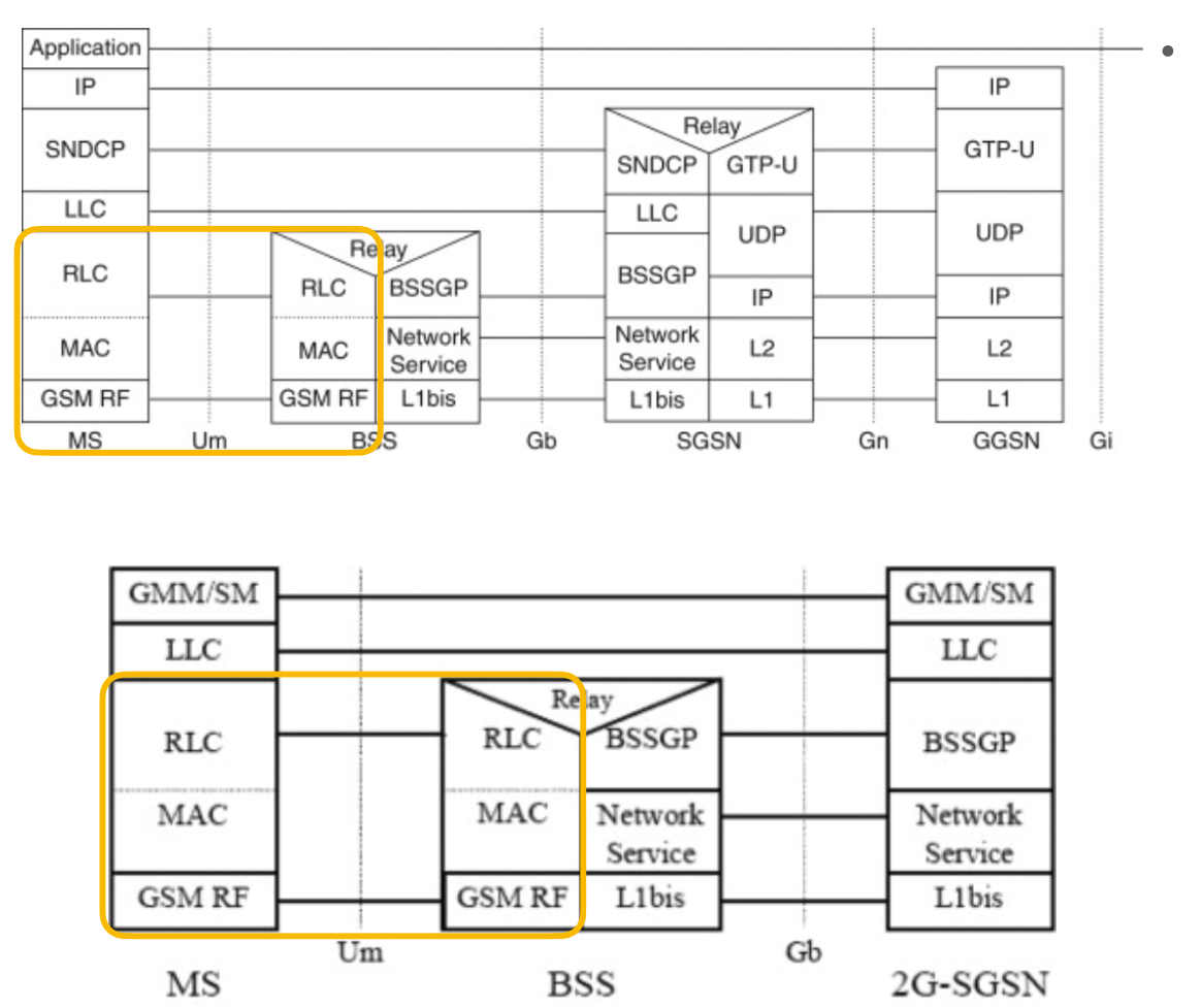
Each of these protocols have their own specifications, frame encoding formats, and procedure definitions, but what they share in common are the functionalities they provide, as a bridge between Layers 1 and 3:
- use smaller (than L3), fixed sized data frames
- as obvious from the above, implement L3 PDU segmentation and re-assembly procedures over L2 data frames
- since L3 protocols are numerous, implement the required multiplexing support for delivering to the correct recipient endpoint (called Service Access Points in 3GPP parlour)
- support unacknowledged and acknowledged modes of transfer and provide support for sliding windows for the later
- in the later, provide the support for in-order delivery and handling sliding ack windows
- besides data frames, implement control frames that carry configuration commands for the layer itself
- in the upper sublayers such as LLC/SNDCP or PDCP in the newer RATS, implement ciphering and compression for the SDUs they carry (and re-assemble)
One of the things that jumps out even from this generic description, is the recognition that this layer (one of its sublayers, depending on the RAT in question, to be precise) is the one in 3GPP responsible for applying ciphering to the enveloped SDUs of the upper layer that it serves.
This means, of course, that all the ciphering (encryption / integrity protection) meant to thwart malicious over-the-air message injection (see: “fake base station” based attacks) only comes into play AFTER the PDUs on these sublayers have been processed. In other words, any processing that pertains to headers of these lower sublayer DATA frames as well as the processing of the control frames belonging to these sublayers are going to include cases where the ciphering is just not of any concern at all.
That itself makes any possible memory corruption vulnerabilities in frame decoding in these sublayers quite interesting.
In L3, most published memory corruption bugs are classic decoding-a-variable-length-field vulnerabilities, where a length representation in a single packet is encoded in some malformed way, whether it be a length value in a TLV encoded field used unchecked or as part of an erroneous integer arithmetic, an ignored grammar constraint on the length of an ASN1 encoded SS or RRC packet SEQOF type field, or a mishandled recursive repetition encoded variable length field in CSN1-using 2G Radio Resource Management packets, to name a few prominent examples from the prior art.
Despite the much shorter frame lengths in L2 usually restricting the practical usefulness of such bugs, some of the same can apply to L2 too. In particular, 2G RLC uses the same CSN1 encoding as 2G RRM.
But there was a more interesting opportunity specific to this layer, that we decided to take a look at: segmentation and re-assembly procedures themselves.
In a way, the idea is to flip the “message lengths are too short for good decoding bugs” logic and look specifically for issues in the re-assembly code.
This, after all, is not a particularly unique idea, classic networking stacks have a rich history of such problems in TCP/IP code as an example. (For one, this finding by Ivan Fratric is an IPv4 fragment re-assembly vulnerability in baseband code itself!)
When it comes to L2 protocols of 3GPP specifications, this area is particularly interesting, because there’s not one standard way re-assembly procedures happen.
Instead, virtually every case defines its own way of implementing the re-assembly procedure: from LAPDm, to GPRS RLC data frames, to E-GPRS RLC data frames, to segmented L3 SDUs carried in various L2 control frames (similarly to how RRM control messages can carry segments for ETWS for example), to segmentation in RLC control frame payloads to allow for larger-than-frame-size control messages field sizes to be accumulated over multiple RLC control frames, and on and on with the newer RATs after 2G as well.
Our first look into this area yielded CVE-2022-21744, an example of the last case enumerated in the previous sentence: a heap buffer overlow in Mediatek basebands found in the processing of CSN1 encoded GPRS Packet Neighbour Cell Data packets, which are meant to allow repeated containers to be sent over multiple RLC control frames and re-assembled into one list. Check out the linked blog post for more details on this vulnerability.
After we looked at Mediatek, we also looked into segmentation vulnerabilities in the context of Samsung Exynos basebands. In this case, we audited the code responsible for handling LLC PDU re-assembly procedures for RLC data frames.
In total, we have identified 5 vulnerabilities, which are outlined in our just published advisories: 1, 2.
In the rest of this post, we describe how we turned a chain of these vulnerabilities into arbitrary remote code execution on Samsung Exynos basebands!
Recap: The Vulnerabilities
CVE-2023-41111 is actually two vulnerabilities rolled into one CVE: a logic bug and an OOB access bug that can be combined to overflow the array the Samsung RLC code uses to store descriptors to LLC data frame fragments, until the condition is triggered to re-assemble them into the original LLC PDU and send to the LLC sublayer.
CVE-2023-41112 refers to a heap overflow vulnerability, caused by the classic copy-first-check-for-exit-condition-after coding mistake in copy loops, that can be triggered during the re-assembly procedure itself. This vulnerability would not be reachable without CVE-2023-41111, which enables the creation of a situation where the list of fragments used to allocate the to-be-reassambled LLC PDU will differ from the list of fragments that are copied together. For details on each vulnerability, check out the advisories!
For the rest of this post, we just need to know that we have a heap overflow primitive where:
- we control the size of the allocation (any up to 1560)
- we control the values written, including the overflowing bytes
- we control the exact length of the overflow (limited by the max value of an RLC data frame size)
- we cannot control the lifetime of the overflowing chunk, which will always get freed immediately following the overflow
Baseband Heap Internals
Before we describe the method we used, a quick recap of the Samsung Exynos baseband’s heap internals.
The general heap implementation for the common malloc/free API comprises several implementations, in particular there is a front-end and a back-end allocator. (More precisely, that are 6 possible heap classes (mids), more than 2 are used, but we can focus on 1 and 4 for this discussion.)
The Font-end Allocator
The front-end allocator (mid4) is a custom pool-based allocator.
The following diagram shows the fields of the 32 byte common heap header that is inline for chunks, used by the front-end allocator:
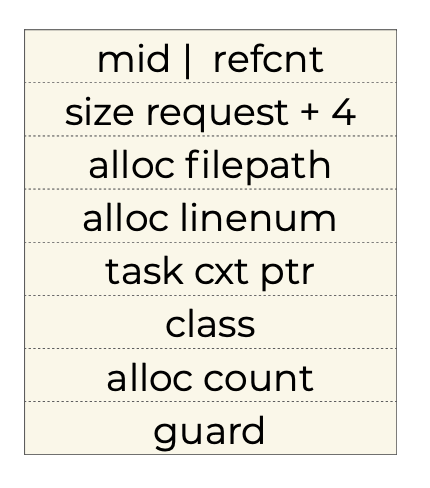
Of note is that the guard value is fix (0xAA bytes).
This is a pool-based allocator, using pool slot sizes of powers of 2, from 32 to 2048.
The diagram below shows the global control structures that define the front-end allocator’s state and behavior:
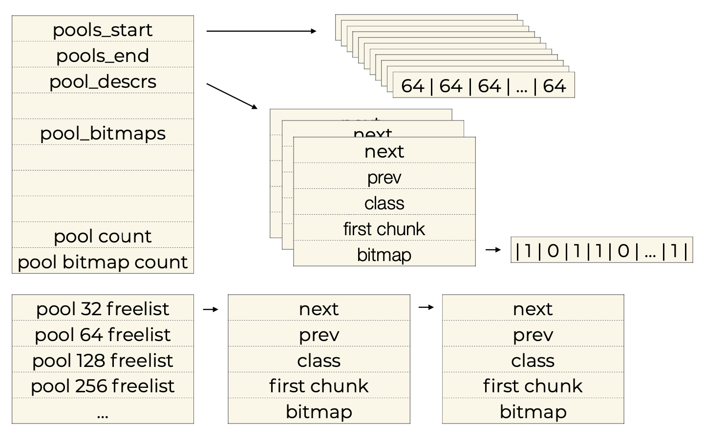
Each pool is 2048 bytes long and the heap pre-allocates a huge amount of pools.
Which is to say, pool instances are not pre-allocated for size classes or otherwise quarantined from one another, but are simply assigned to a given size class on demand, whenever a fresh pool instance is needed.
That happens when the available pool lookaside list for the given size class is empty.
Once a pool is chosen during allocation, the first available slot is always the one picked.
As usual, the freeing simply means flipping the corresponding bit in the bitmap descriptor belonging to the given pool instance.
The Back-end Allocator
The back-end allocator (mid1) is much simpler and less unique: it is a simple old-school coallescing dlmalloc.
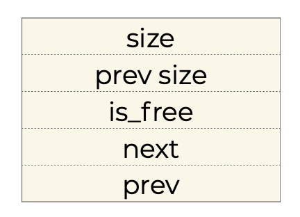
This is the format of the 20 byte inline header for mid1 chunks:
Shannon Heap Exploit Technique: Heap Overflow to Write4
As several others have already noted publicly (not that it matters, but we were also aware of and documented this method to Samsung in our report before those publications last year), the Achilles’ heel of the back-end allocator is that its free chunk unlinking procedure (during free chunk coallescing) includes the classic unsafe-unlink write4 weakness.
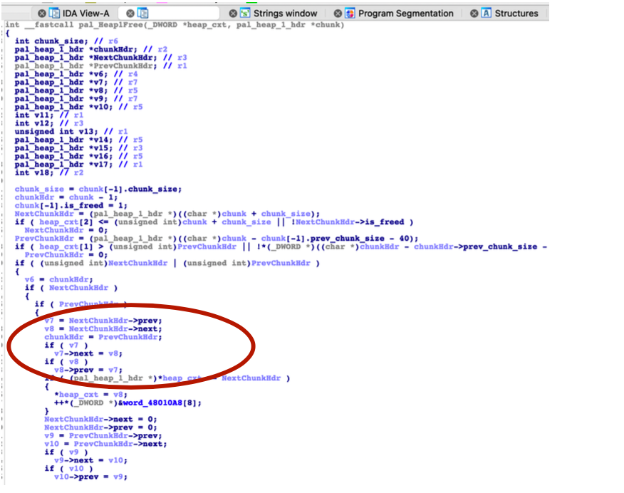
In this section we quickly recap how this standard technique is triggered in the Samsung Exynos baseband heap.
Since all allocations that we work with for our exploit happen on the front-end allocator, we need a way to make a free() call that we target use the back-end algorithm.
As it’s been also described before for this technique, this is also straightforward. The Samsung Exynos baseband RTOS uses a common free() API, which directly uses the provided chunk’s first field (mid) to decide which allocator type the freed chunk belongs to, and then triggers the front-end vs back-end free algorithm on it accordingly.
(Since the entire front-end heap arena is allocated as one huge chunk out of the back-end heap, it follows that every legit front-end allocation’s address will fall within the valid range for the back-end heap as well, so this isn’t an issue either.)
Therefore, in order to make use of the write4 technique, all we need to do is corrupt the first field (mid) of the header.
One wrinkle, that is confusing at first, is that the front-end vs back-end free functions that are called by the wrapper free function on the chunk behave differently.
Regardless of which one is chosen by the wrapper free, the pointer passed in is to the entire chunk, i.e. to the start of the common header, with the mid field as its first field. However:
- when the front-end heap free is chosen, the function treats it as such, a pointer to a buffer starting with a common heap header,
- when the back-end heap free is chosen, the function treats it as a pointer to the payload part of a back-end allocated chunk, meaning it subtracts the size of the back-end heap header (20) from the passed pointer to get the location of the header.
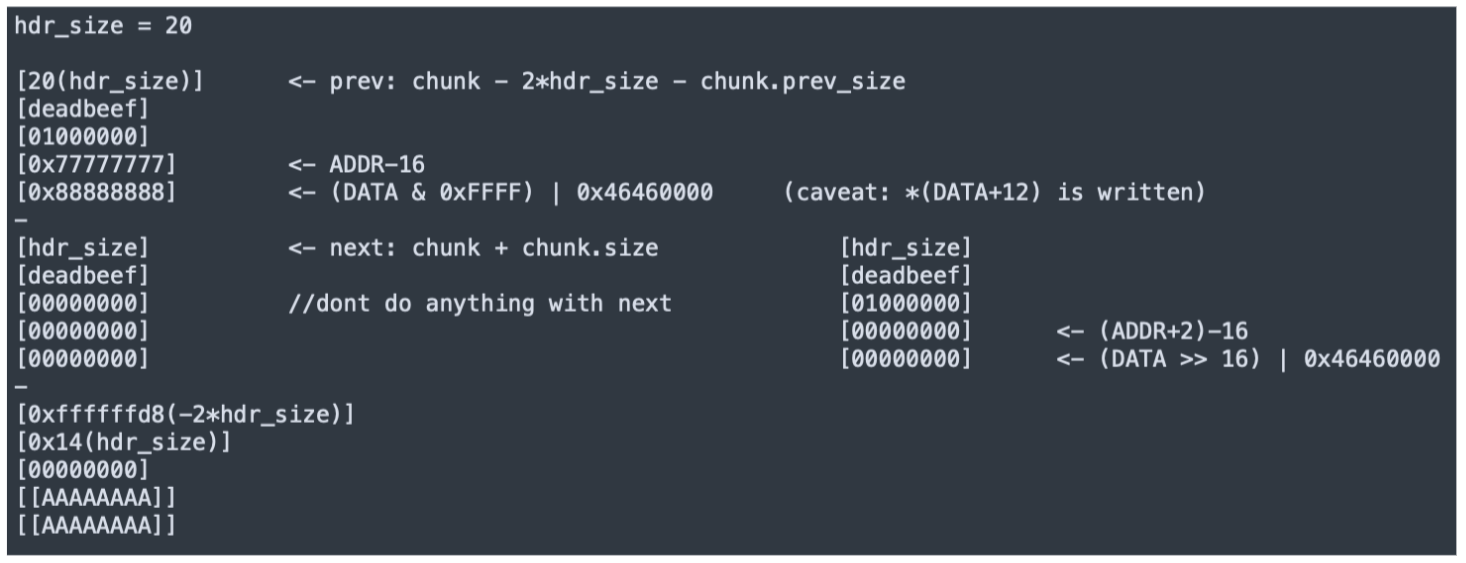
In other words, in order to create a fake back-end chunk (with which we can trigger an unsafe unlink coallescing), the fake back-end chunk header has to be placed in front of the overflowed chunk, and the the overflowed chunk’s common heap header’s mid field has to be replaced with 1.
The following contextualizes how the overflowing chunk’s relevant offsets towards its end need to be populated in order to trigger write4s during the unsafe unlink that we force:
Heap Shaping
The next step was figuring out a way to reliably trigger the write4. There are two complicating factors:
First, the baseband heap is pretty busy, in particular on the control flow path of processing RLC data frames itself.
Second, in the case of this vulnerability, the overflowing chunk is always freed right after the overflow happens. Why this happens is that the chunk we are overflowing from is the re-assembled LLC PDU, which is then passed to the LLC sublayer from RLC, which then will either discard it (if the LLC header/footer values of the PDU are invalid), or it will take out the SDU from the PDU by removing the headers and footer. This SDU becomes a new allocation, to which the content is copied, with the original chunk containing the re-assembled LLC PDU then discarded.
Due to the second one, we always must reclaim the chunk we overflowed from before triggering the free of the chunk after it.
But do to the first one, getting back the same exact chunk reliably is not that straightforward - not to mention getting our chunk next to an allocated chunk whose freeing we can trigger explicitly when desired.
This later point is again crucial, since the free (of the overflown chunk) mustn’t occur before we managed to re-claim the overflowing chunk.
For this reason, we had to look for ways to control the baseband heap layout in a reliable manner.
As it happens, we found a perfectly capable heap shaping primitive within the same codebase that we’ve been looking at: Layer 2 sublayer-to-sublayer data packet transmission procedures.
Heap Shaping with LLC
In the previous section we touched upon what happens once the re-assembled PDU is forwarded from the RLC sublayer.
To recap, the PDU arrives at the LLC layer, which is essentially a multiplexer layer, as shown by the following Figure:
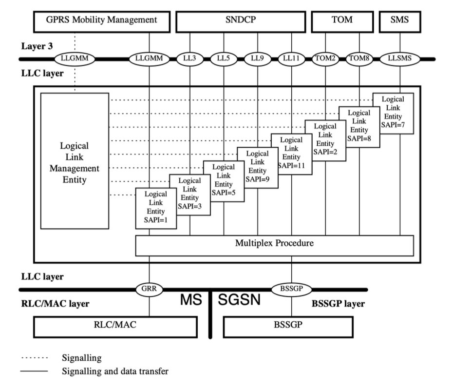
As we can see, the primary task of the LLC layer is to identify which receiver in Layer 3 should the packet be forwarded to. The recepient in practice can be GPRS MM (control plane), SNDCP (sublayer wrapping IP, the radio technology stack equivalent of Ethernet layer, if you will), or SMS (yes, SMSes can be sent over GPRS too in 3GPP).
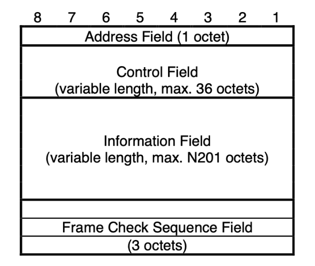
The multiplexing is done by extracting the SAPI (Service Access Point Identifier) value from the LLC PDU header. But the LLC packet format includes additional fields in the header/footer, which add:
- a checksum, for error detection/correction
- an ability to send control packets (U frames, S frames) in order to configure the LLC sublayer behavior, including
- state management for each SAPI, supporting both Unacknowledged (UA) and Acknowledged Mode (AM)
In UA, the LLC sublayer is a true multiplexer, acting like UDP.
However in AM mode, each packet (I frame) can be acknowledged, and a window is maintained for acceptable I frames, within which window the LLC sublayer guarantees in-order delivery for the upper layer recipient.
Bsaed on the specification, the network has a great deal of control over the LLC operation modes:
- the window size can be configured by the network using U frames
- the switch from the default UA mode to AM mode can be directed by the network also by U frames (specifically, an SABM message), individually for each SAPI (but only allowed for the SNDCP designated SAPIs: 3, 5, 9, 11)
- acknowledgments for individual I frames are still dictated by the sender: even if AM Mode is turned on, an I frame is only acknowledged if the sender requests it
Luckily, the AM implementation in Samsung’s code presents us with a great heap shaping primitive:
- every out-of-order arriving packet is stored in a linked list (not the original re-assembled allocation, but the stripped out LLC SDU)
- whenever a packet arrives, after extracting the SDU and placing it on the linked list, each in-order one is sent to the SNDCP layer; this sending also uses data copying which results in the freeing of the SDU allocation that was stored in the linked list
In other words:
- if we skip the first index of the current window, we can spray
window_size-1number of allocations, - whenenever we want to free the allocations, we can trigger the freeing by sending the I frame with index 0 of the receiving window.
And since we have 4 SAPIs to play with, we can engineer a checkerboard allocation by sending I frames to alternating SAPIs and then sending index 0 for only one of the two SAPIs used.
This way, we can create a situation where the subsequent overflowing allocation will be guaranteed to fall in front of a chunk that we’ll be able to control the free event for.
One wrinkle to keep in mind: the overflowing allocation happening in RLC has a different allocation than the stored allocations, since it includes the stripped out LLC header and footer. We can use that size differential to our advantage and “bump out” the RLC allocations for the heap shaping LLC PDU I frames that we send, making sure that those temporal allocations don’t interfere with the pools for the size class that we engineer our heap feng shui for.
Building A Working PoC
As we can see, the exploit will have some fairly involved steps, which is a fancy way to say that we expected to end up with a poc using some “magic number” of iterations of heap filling (spraying) steps, as typical in cases like this.
In order to test such an approach, we needed a way to inspect what was happening during attempts.
Luckily for us, the Samsung Exynos baseband heap already has a very powerful built-in debugging feature. By turning on Debug High mode for the baseband (same functionality since the days of Breaking Band), we get an extra behavior in the heap malloc and free wrapper APIs: besides storing the allocation/free filepath and linenumber information into heap chunk headers, an in-memory ringbuffer of heap events is also populated.
Even better, also in Debug High mode, the baseband memory can be easily ramdumped, both on demand from the Android UI even and automatically whenever the baseband crashes. With the ramdump file, it’s trivial to extract the ringbuffer and from it reconstruct a flowchart of sequential heap events.
We built a simple Ghidra script to process ramdump files and create an old-school ASCII art visualization of heap states. Here’s a screenshot of the script in action:
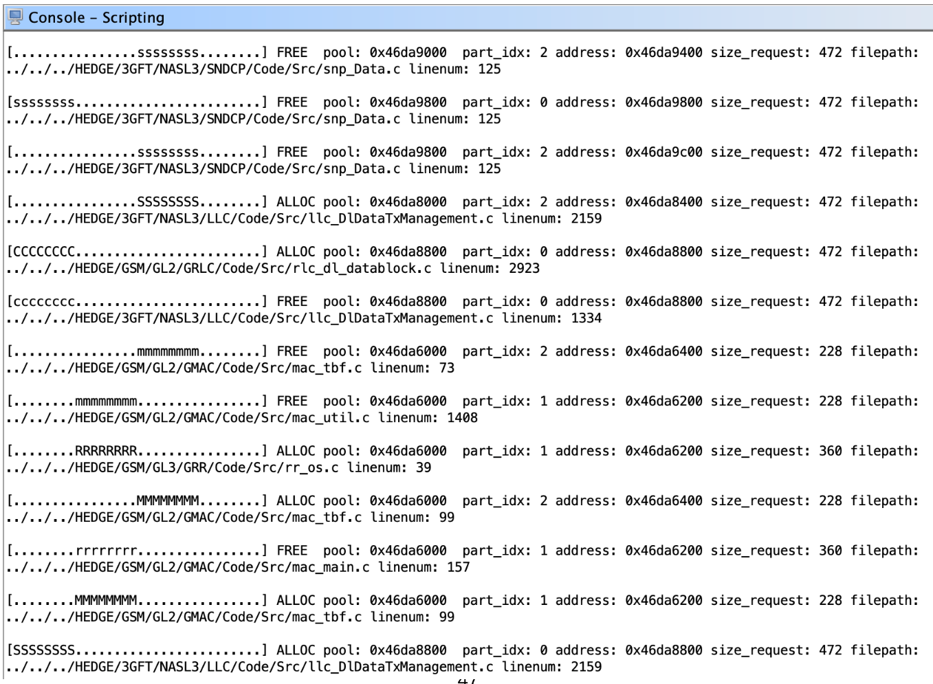
Using this tool, we were able to iterate spraying variations using the LLC SAPIs, until we found a combination that reliably “smoothed out” the busy pools for the chosen size class and then created the checkerboard pattern of allocations.
Exploit Plan
To summarize, our exploit plan will contain the following steps:
- turn on LLC AM mode by sending SABM for each of the 4 SDNCP SAPIs
- use SAPI 3 to spray the heap for size class 512 (using an I frame size such that the entire LLC PDU falls into 1024 class already, but the stored away LLC SDU fits 512)
- use SAPI 5 and 9 to create a checkerboard pattern of allocations of fully sprayed pools for the same class
- free all LLC frame allocations for SAPI 5 by sending in the LLC PDU with index 0
- send the malformed RLC data frame to trigger the heap overflow and replace the LLC PDU allocation’s heap header’s mid with value
1(this overflowing chunk itself will not have a valid checksum when its last 3 bytes are interpreted as such in the LLC sublayer, so it gets discarded right away without extraction of an LLC SDU from it) - use SAPI 11 for re-spraying the heap and reclaiming the overflowing chunk, with the payload of the SAPI 11 LLC PDUs containing the fake
mid1headers as needed for the write4 - finally, trigger free on SAPI 9 by sending LLC PDU with index 0
The steps visualized, from our presentation:
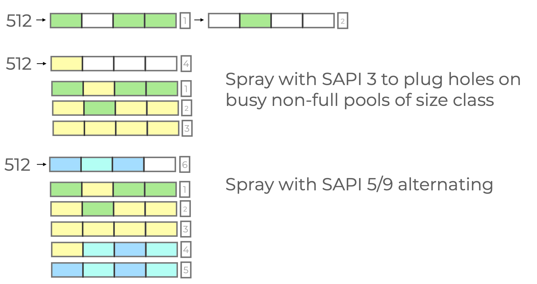
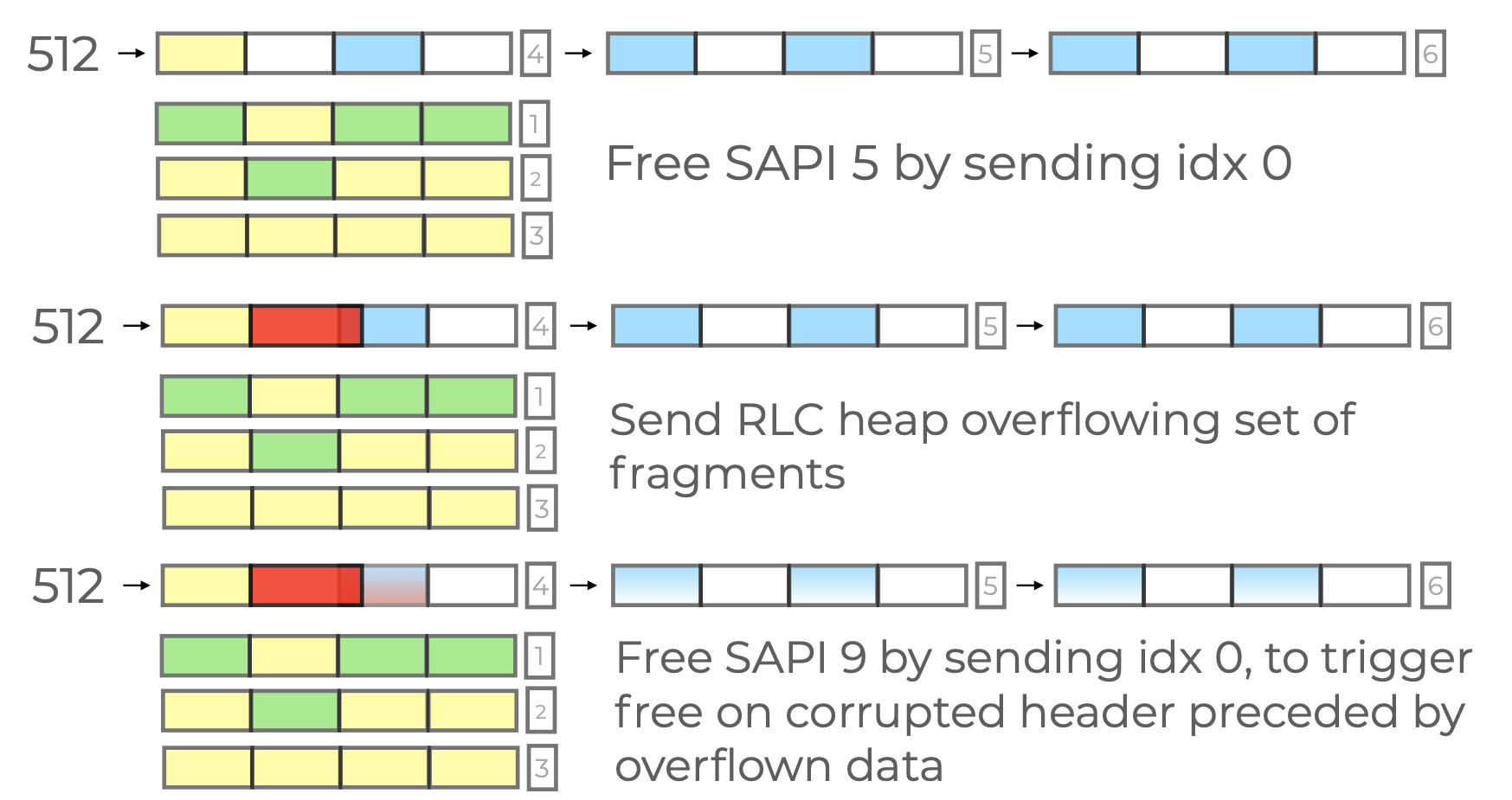
(Note: these pictures, that are also in our slidedecks, ommit the re-spraying step between the final two steps to reclaim the overflowing chunk’s slot before triggering the free that results in the write4.)
Heap Shaping Improvements
So did this work? Well, sort of. We definitely had a PoC that succeeded at triggering a write-4 sometimes, but it wasn’t reliable enough.
In practice, we addressed a few more wrinkles that came up when testing PoCs.
The first difficulty was that in practice, Samsung Exynos basebands really don’t seem all that robust when it comes to handling large volume of traffic. Even with a run-of-the-mill SDR and a straightforward, python API based injection implementation, it turns out to be way to easy to “flood” the baseband with messages to the point where frames get dropped (unprocessed by the baseband).
At first, we simply wanted to take advantage of LLC AM mode to “rate-limit” our sending, by requesting (and awaiting) the acknowledgement for each I frame we have sent. This worked well, except for one problem: we have learned that the Samsung implementation allocates a context structure for each Traffic Block Flow (TBF) in the MAC sublayer and this allocation happens to fall into the same pool size that we targeted:
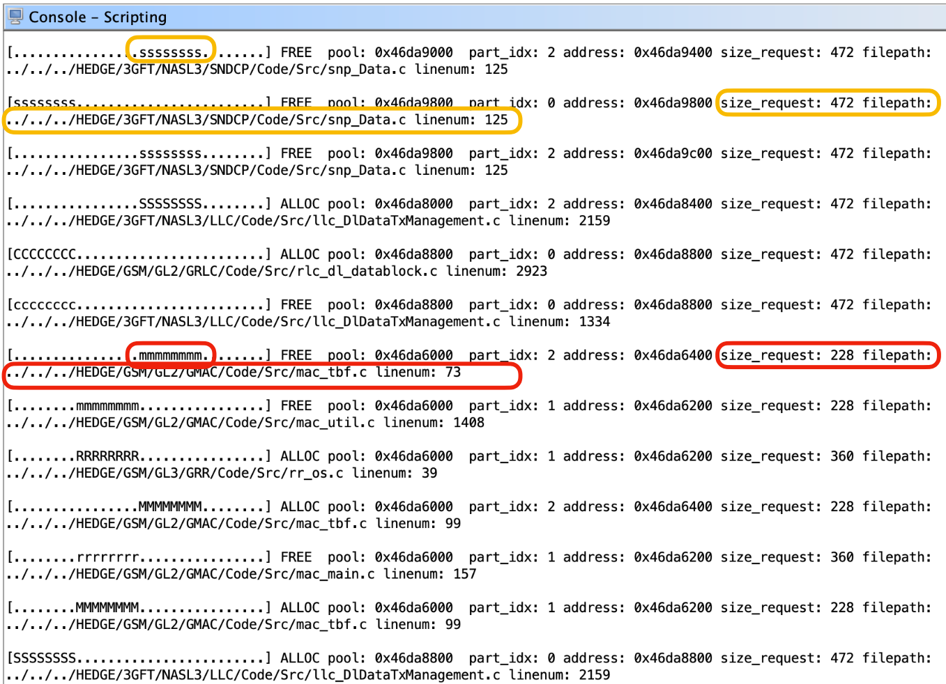
This is a real problem because, if we keep waiting for ACKs, then the behavior we get is repeated creation (and deletion) of new Uplink (UL) TBFs, which means noise over out attempted heap shaping.
Several options exist, such as targeting a different pool, but in our case we went with the KISS method and experimented with sending delays until we were satisfied that the baseband will properly process each LLC I frame.
On a related note, once we realized the issue with allowing UL TBFs, we also had to address the fact that the phone itself will try to create Internet connections quite often. These obviously result in additional UL (and DL) TBF traffic at the LLC sublayer. We can also opt for a straightforward solution here: by preventing the PDP Context Creation during GPRS Attachment, we can cause the phone to not even attempt any Internet traffic, because from Android’s size, it will look like there’s no cellular data connection.
It’s actually worth stopping here for a second and think about the implications: the baseband allows us to switch LLC AM mode for SAPIs 3/5/9/11 and send LLC I frames containing purported SNDCP packets - despite the fact that no PDP Context has been created! For our 2c, this is a state machine contradiction that shouldn’t be allowed. But it is.
Finally, we also mention the most annoying problem: sometimes RLC frames themselves just get dropped. Frame ACK/NAK is a default feature at the RLC layer, and the proper Osmocom code handles this correctly for the RLC frames that it sends out by design. Our original RLC data and control frame injection patch was lazier, UDP-like, if you will. An ideal solution would keep track of the RLC frame ACK/NAK responses that arrive and re-attempt sending for what has failed to be received.
In the end, we added an additional patch to the Osmocom code that allowed our PoC to count the number of received Acks for RLC frames and we added another KISS improvement to deal with RLC frame dropping resulting in “disappearing” upper sublayer control plane messages (such as GPRS SM and MM and/or LLC U frames): simply attempting the injection of the necessary initial control messages (such as the LLC SABM U frame for each SAPI) in a loop until they all succeeded.
Overcoming Entropy
Finally we had a PoC that worked reliably enough that we were able to repeat write4s, i.e. creating a primitive to overwrite N bytes instead of 4 bytes only. The final piece was creating arbitrary code execution from that.
Samsung basebands have no ASLR, so for a given firmware variant a lot of addresses will be fix: code, BSS, stack frames.
Given that, if the device version + firmware variant is known, nothing stops an exploit with the building blocks described so far to reach reliable code execution by repeatedly triggering the heap overflow to overwrite chosen memory addresses with chosen values, 4 bytes at a time.
However, while the device type can be simply extracted from an IMEISV Identity Request’s response, querrying a Samsung phone for its exact firmware variant is not a given. There can be various ways to approach this fingerprinting challenge.
The simplest idea would be bruteforcing. For example, we could spend time on collecting firmwares, analyzing variance, and finding out whether we have a low enough bits of entropy in location variance of various in-memory structures whose changed values can be reflected back, such as the Identity values stored in memory that are returned in MM Identity Responses.
But this is obviously non-deterministic, may cause crashes or be otherwise unreliable, and would in either case require a larger firmware database maintenance effort.
As it turns out, we can do better then fingerprinting: we can make exploitation work even without knowing the exact firmware version or even precise device version!
For the explanation let’s focus on newer devices (S20+) that use an MMU (there are techniques for blind exploitation on older, MPU based device variants as well but this is skipped for brevity).
In Samsung Exynos basebands, the RTOS uses a standard ARMv7 2 level page table format. The runtime accesses the page table at a known, always fix, device and firmware version agnostic, and writable address (0x40008000).
Crucially, the baseband RTOS doesn’t distinguish privilege levels for its tasks: all baseband code runs in supervisor mode, thusly able to read/write the page table directly! So, despite the baseband RTOS having a microkernel and handling SVC calls (syscalls) via its VBAR (which points to 0x40010000), all code runs in context that can modify the virtual memory where the page table is stored.
Therefore, we can always just choose an arbitary location that is RW, repeatedly use the arbitrary write to fill shellcode there, and then write into the page table at the right entry slot to make that address XN=0. Now we have shellcode at a known address, all we have to do is jump to it.
Alternatively, if we have a good enough heap shaping primitive (like we happen to have), we can use the fact that the size of the heap area is uniformly large enough to overcome firmware version-caused entropy, i.e. by spraying enough pages, we can make sure that a chosen VA will point to our sprayed input. Then, we can turn the address permissions into RWX.
Better yet, since the page table is writable, we can modify the AP properties of the 0x40010000 page to RW from RO with a single page table entry write.
This allows us to in turn write into where the VBAR is pointed and replace for example the syscall handler. This is a great target for “firmware agnostic” exploitation, because the first page from the start of where the firmware runtime is mapped contains instructions that aren’t affected by firmware variance.
This is immediately useful because in the baseband, there is exactly 1 used syscall: abort.
Therefore, we can replace the syscall handler with a pointer to our staged shellcode and then trigger the same heap vulnerability again, but this time constructed “less carefully” i.e. triggering an abort on it like the PAL_MEM_GUARD_CORRUPTIONPAL_MEM_GUARD_CORRUPTION abort e.g. by intentionally not covering the 4 guard bytes with “AA” in the overwrite.
In fact, we can even use the abort state itself: whenever PAL_MEM_GUARD_CORRUPTION abort is reached, the faulting allocated chunk will actually have a pointer point to it in R7.
So now a hijacked abort handler, replaced with a register jump instruction, can jump straight into our shellcode and arbitrary code execution is achieved. (Ok, technically, “straight” means a few assembly instructions, needing a few write4 triggers, to address the BSMA VA transformation that is explained below, as well as to skip over header fields of an allocated chunk to make this work well.)
An abort is actually also trivially recoverable at the point of the syscall entry, so continuation of execution is reachable from here quite conveniently as well.
Alas, we can manage to execute shellcode without any ROP and without having to know which firmware version the exploit code will run on!
The “Baseband Space Mirroring Attack”
Except … not quite. When we tried page table rewrites in practice, we have found that it didn’t quite replicate. No matter that we replaced PTE values, the mapping permission behavior didn’t change.
Turns out, the issue is caching. Likely because the Samsung baseband mostly uses large pages for almost the entire address space, the number of valid PTE entries is fairly small. We suspected that the issue was that the TLB walks already cache all results, to the point where no valid VA read/write fetch will cause a new access to the memory where the page table itself is stored. The MMU is MMUing, in other words.
This is where (name borrowed from KSMA) baseband space “mirroring” comes in.
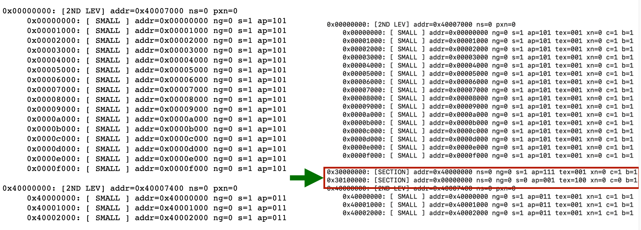
The idea is to pick an arbitrary address, which is not normally mapped into the baseband address space, and then instead of overwriting the targeted PTE, create a new PTE entry for the fake virtual address but backing the same targeted physical address, this time of course using our own set of desired permission bits.
The picture below shows an example of a fake VA-PA mapping from 0x30000000 to the original 0x40000000 injected into the page table with the simple write4 primitive:
Over-the-Air Implementation
In order to demonstrate the exploit, we used a modified Osmocom codebase together with a stock bladeRF software-defined radio. For this, we extended our previously implemented Osmocom patch that adds a scripting API for sending arbitrary messages and filtering/inspecting incoming ones, which we previously implemented for NAS layer injection.
The FOSS Osmocom stack already supported GPRS RLC in general, but we had to add some extensions to make the exploit work:
- support for injecting arbitrary RLC data or control frames into an existing TBF or into a newly created one (added to
osmo-pcu) - support for enabling LLC AM mode by sending a custom LLC SABM and checking the response (upstream code partially implemented GPRS LLC AM mode support, but it was incomplete; added to
osmo-sgsn) - support for sending arbitrary LLC PDUs (used for the heap shaping, added to
osmo-sgsn)
DEMO
To close it out, here is a demo video of our Over-the-Air exploit in action! The PoC achieves the following:
- triggers the heap overflow repeatedly, with the heap layout shaped before each attempt, in order to modify the page table using the “BSMA” attack, making the heap executable and a target function handler writable
- sprays the heap with our payload shellcode
- overwrite the handler (reachable by an otherwise innocuous OTA message) to create a convenient hook for executing code, redirecting it to the payload shellcode
- trigger the “backdoored” handler a few times to demonstrate the added payload in action